Modern battery systems, particularly those employed in demanding applications like large energy storage units, rely heavily on sophisticated BMS diagnostics to ensure safe and efficient operation. When these systems flag anomalies, a systematic diagnostic approach is crucial to pinpoint the root cause. This case study details the investigation of a specific fault scenario within a 1P52S-314Ah battery module, where the BMS main control computer reported multiple alarming messages.
Initial Observations and Fault Reports
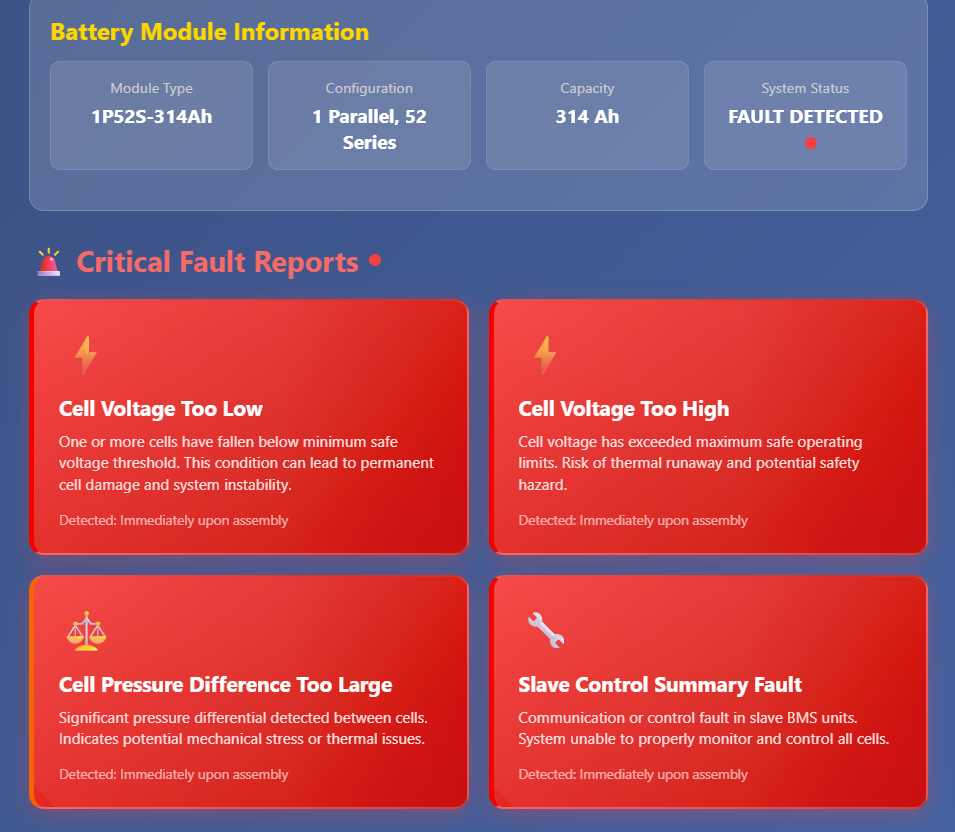
Upon assembly of a 1P52S-314Ah battery module, the BMS main control computer, responsible for reading voltage and temperature samples, immediately detected irregularities. The system issued a series of critical alarm messages, including:
- “Cell voltage is too low”
- “Cell voltage is too high”
- “Cell pressure difference is too large”
- “Slave control summary fault”
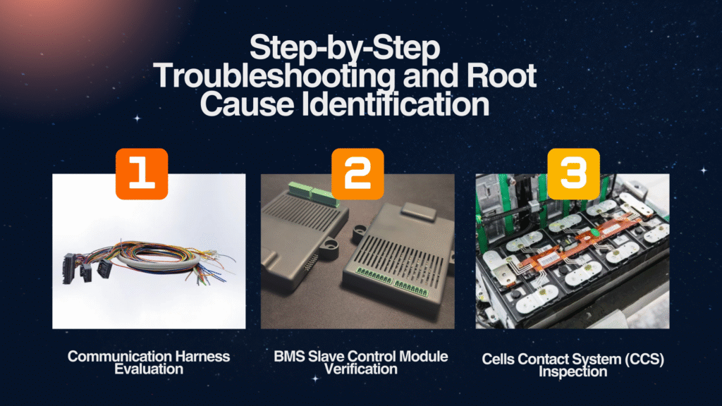
These alarms collectively pointed to abnormal voltage readings from two specific battery cells within the module. To efficiently identify the problem, the investigation team decided to systematically explore three primary potential culprits: the communication harness, the BMS slave control module, and the Cells Contact System (CCS).

Step-by-Step Troubleshooting and Root Cause Identification
The diagnostic process involved a methodical elimination of potential issues:
1. Communication Harness Evaluation
The first step in the troubleshooting process was to assess the integrity of the communication harness. This harness is vital for transmitting data, including cell voltage readings, from the individual battery cells to the BMS slave control module and subsequently to the main control computer.
The team replaced the existing communication harness with a spare, new wiring harness and connected it to the BMS slave control module. However, even with the new harness in place, the voltage sampling for the two problematic battery cells remained abnormal, and the main control computer continued to report the identical fault information. This conclusive test allowed the team to rule out the communication wiring harness as the source of the problem.
2. BMS Slave Control Module Verification
With the communication harness eliminated, the focus shifted to the BMS slave control module itself. This module is directly responsible for acquiring cell data and processing it before sending it to the main BMS controller.
To verify the functionality of the suspect BMS slave control module, it was removed from the faulty battery module and installed onto a different, known-good battery module. If the voltage sampling on this new module proved to be normal, it would indicate that the BMS slave control module was functioning correctly and was not the source of the original issue. (The text implies this step would have confirmed the slave module’s integrity if successful).

3. Cells Contact System (CCS) Inspection
Having ruled out the communication harness and presuming the BMS slave control module was verified as operational, the investigation then homed in on the Cells Contact System (CCS). The CCS is an integrated busbar system that facilitates electrical connections and voltage sensing points for individual battery cells.
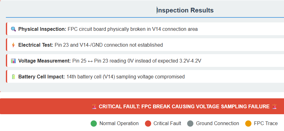
The team proceeded by opening the BMS maintenance panel and carefully removing the battery module box cover to gain access to the CCS components. Using a multimeter, they meticulously measured the voltage sampling values corresponding to each pin of the CCS connector.
During this detailed inspection, a critical anomaly was discovered: the voltage measured across CCS connector pin 25 and pin 23 (which corresponded to the 14th battery cell) was 0V. Further investigation revealed that pin 23 and the V14-/GND connection of the second module were not connected, despite being designed to be. A thorough physical inspection then pinpointed the exact cause: the FPC (Flexible Printed Circuit) circuit board in a specific area of the CCS was broken. This physical break directly resulted in the V14 sampling voltage reading as 0V, triggering all the reported alarms.

Conclusion and Resolution
The systematic diagnostic process successfully identified the broken FPC circuit board within the Cells Contact System (CCS) component as the root cause of the abnormal cell voltage readings and the cascade of BMS alarms. The resolution to this issue requires the replacement of the faulty CCS component. This case study underscores the importance of a structured approach to troubleshooting complex battery systems, emphasizing the critical role of each component in ensuring the overall health and safety of battery modules.


